|
By : Jim Pinto,
Instruments & Control Systems, June 2000 Click here for a copy from the I&CS website |

|
Temperature is the most-measured process variable in industrial
automation. The two prime sensors used to measure it are resistance
temperature detectors (RTDs) and thermocouples (T/Cs). For relatively
narrow temperature ranges, a variety of other temperature sensors can be
employed. Examples include: diode or transistor junctions, which have a
relatively narrow range of measurement and are commonly used to
measure the temperature of electronic equipment; thermistors, positive or
negative temperature coefficient resistors, which offer a maximum range of
measurement up to about 200-300
A closer look at RTD technologyBecause of its wide temperature range (up to about 800°C) and relatively uniform characteristics, platinum is the most common material from which RTDs are constructed. Where cost is a factor, nickel or copper RTDs are sometimes used, but these sensors provide a relatively low range of temperature measurement.
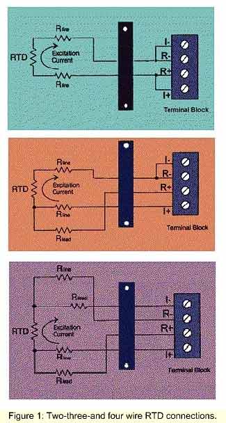
When an RTD is connected to a signal-conditioner or controller, it is connected as one arm of a bridge, through which an excitation current passes to develop a voltage signal that varies with temperature. The maximum excitation current is determined by the self-heating within the RTD, which will cause measurement inaccuracy; this limits the maximum signal for a required measurement temperature range-i.e., simply increasing the excitation does not yield a greater signal. To produce a higher-level signal for indication, recording, alarms, or controls, a separate signal conditioner is needed. Some PLC and PC I/O cards allow direct RTD connection with integrated signal conditioning. Please note that RTD connection leads themselves cause errors due to the resistance of the wires and the change in that resistance, especially when very long lead-lengths are used. This is minimized or eliminated through the use of three-wire and four-wire RTD connections (Fig. 1). The change in resistance with temperature for all RTDs is nonlinear. For accurate conversion to temperature, a good signal conditioner or two-wire transmitter includes some form of linearizing, usually a first-approximation analog feedback technique or, if the instrument is digital, a segmented look-up table that converts the input voltage reading directly to temperature. A good signal conditioner, controller, or RTD I/O card can provide temperature measurement accuracy to a fraction of one degree over a fairly wide span of measurement, comparable with the accuracy that can be attained with a good platinum RTD. Whatever the material and construction, an RTD is still relatively bulky, and therefore cannot measure temperature at a point. On the other hand, this technology provides an excellent means of measuring the average temperature of a surface by spreading the resistance wire over the surface. The use of a platinum RTD may be preferred when a temperature measurement accuracy of better than 1°F or 1°C is required. However, for contact measurements of temperature above about 800°C (the maximum temperature at which platinum RTDs can be used), a thermocouple is the primary choice. Thermocouple temperature measurementT/Cs measure temperature by generating a millivolt signal proportional to the temperature difference between the junctions of two dissimilar metals. One junction is typically encased in a sensor probe at the point of measurement, the other junction is connected to the measuring or control instrument.
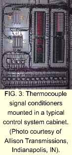
Waiting, warm-up prolong calibration proceduresWhen the ambient temperature changes, most T/C measuring instruments may drift by a few degrees. Typical T/C-input instruments take from several minutes to a half-hour to stabilize to within a couple of degrees. In some applications, a drift of a few degrees doesn't matter, but when several hundred instruments are being calibrated, prolonged warm-up time makes the job considerably more difficult.Conversion to direct temperature readoutThe most common T/Cs are types E, J, K, R, S, and T. However, there are many others, each of which offers special characteristics for use in a variety of applications-high or low temperatures, materials that are best suited to specific environments, and so on.All T/Cs have somewhat nonlinear characteristics (i.e., in terms of millivolt output relative to temperature) and a direct readout of temperature will provide accuracy only within about 20-30°C, depending on the temperature span. To read temperature over the complete span of the thermocouple, the measuring instrument (Fig. 3) requires linearization. With a conventional analog instrument, the transfer characteristic is linearized in perhaps five to ten segments, providing improvements to within a few degrees. Digital signal conditioners use a look-up table that can provide direct digital readings with an accuracy of a fraction of 1 °F or °C. Multipoint I/O cards for PLCs or PCs typically condition and linearize all inputs together, and are usually designed for just one type of T/C. General-purpose signal conditioners are programmed, either manually (by a DIP switch) or via smart PC software, to allow connection to virtually any type of T/C.
IsolationRTDs and T/Cs typically are isolated from their sheaths, though long lead lengths may be grounded inadvertently, and it is important to provide complete isolation from ground and power. Ground loops, with inputs and outputs grounded in different places, can cause significant errors and even damage. Therefore, it is a good idea to ensure that the instruments to which your temperature sensors are connected provide complete isolation from power and ground.For multipoint measurement, most PLCs and dataloggers do not provide isolation between one sensor input and another (they typically use just one common power supply). Therefore, separate four-way isolating signal conditioners (input/out put/ power/ ground) can save a lot of trouble by eliminating the possibility of future, inadvertent grounding problems. Which should you use-RTD or thermocouple?If you need accuracy of better than 1°F or °C at temperatures less than about 800°C, and can afford the additional cost, a platinum RTD should be your choice for temperature measurement. However, if you only need accuracy of a couple of degrees, you might prefer the lower cost, point contact size, and versatility of thermocouples. Unless you want a noncontact IR device, if you are measuring temperatures above about 800°C, you need a T/C. However, if you do use T/Cs, make sure that the instrumentation to which you connect has the cold junction characteristics you need for your application.One solution to cold-junction errorTo minimize cold-junction error, instrument engineers and technicians typically perform instrument calibration a few minutes after the measuring instrument is powered up, allowing the cold junction to stabilize after warm-up. But this can only be done on the test bench. In the field, measurement accuracy is still affected by outside temperature transients-for example, when adjacent instruments such as programmable controllers, recorders, and power controllers are switched on or off, or when the system's cabinet doors are opened. To overcome these errors, instrument engineers typically wait several more minutes for the entire cabinet or system enclosure to stabilize before calibrating in-situ thermocouple measurements. Any changes or disturbances will cause further delays.In many applications, traceable calibrations of equipment are required at least annually, involving perhaps several thousand instruments. The calibration of thermocouple-input instrumentation can be quite time-consuming if each instrument requires several minutes to warm up or stabilize. This highlights the importance of thermocouple-input design that provides good accuracy with minimal warm-up time after the system is turned on, as well as good repeat accuracy for extended periods.
As shown in Fig. 2, standard cold-junction compensation operates with one measurement-CJC-A, while Instant Accuracy operates with two-CJC-A and CJC-B, and calculates the temperature at the actual cold-junction. Here's how it works. You cannot measure the exact temperature of the terminals, but you can predict what that measurement is by measuring two points along the path of the temperature variation and calculating the temperature of the third point-the cold junction. It's almost like the cold junction is not measurable-on the other side of a wall-but the measurement is calculated by extrapolation of the other two measurements. Of course, the calculations may be different for different physical geometry, but in any instrument with fixed geometry, the calculation remains the same and the overall thermocouple measurement accuracy is improved considerably.

|
 An RTD is constructed by winding a length of pure platinum (or other metal)
wire on a small ceramic tube, inserted at the point of measurement. The winding
is done tightly, but in a format that causes no physical stress under temperature
variations. The thickness and length of wire determines the total resistance.
The standard is 100 ? at 0°C, though a more sensitive RTD may
be up to 1000 ? or more, to get a larger signal.
An RTD is constructed by winding a length of pure platinum (or other metal)
wire on a small ceramic tube, inserted at the point of measurement. The winding
is done tightly, but in a format that causes no physical stress under temperature
variations. The thickness and length of wire determines the total resistance.
The standard is 100 ? at 0°C, though a more sensitive RTD may
be up to 1000 ? or more, to get a larger signal.
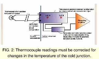 Since the ambient temperature changes in the field or control room where
the measuring instrument is located (typically the cold junction), the
actual millivolt signal generated by the T/C fluctuates accordingly, causing
a "cold-junction error." To offset this error, the temperature at the
instrument terminals is measured and a compensating signal, the
cold-junction compensation (CJC), is inserted (Fig. 2). The overall
measurement accuracy depends on the accuracy of cold-junction
compensation with varying ambient temperature over the normal
instrument operating temperature range.
Since the ambient temperature changes in the field or control room where
the measuring instrument is located (typically the cold junction), the
actual millivolt signal generated by the T/C fluctuates accordingly, causing
a "cold-junction error." To offset this error, the temperature at the
instrument terminals is measured and a compensating signal, the
cold-junction compensation (CJC), is inserted (Fig. 2). The overall
measurement accuracy depends on the accuracy of cold-junction
compensation with varying ambient temperature over the normal
instrument operating temperature range.
 Problems arise because typical electronic instruments (for example, signal
conditioners, recorders, displays, and controllers) cannot really measure
the actual cold-junction temperature; they simply try to get as close as
physically possible-but not close enough to eliminate inaccuracies of at
least a few degrees. The use of terminal-blocks and plug-in connectors
typically exacerbates the problem-because the actual thermocouple cold
junction becomes more physically separated from the cold junction sensor.
The cumulative effect of ambient temperature and other variations may be
five to ten degrees, which can be significant.
Problems arise because typical electronic instruments (for example, signal
conditioners, recorders, displays, and controllers) cannot really measure
the actual cold-junction temperature; they simply try to get as close as
physically possible-but not close enough to eliminate inaccuracies of at
least a few degrees. The use of terminal-blocks and plug-in connectors
typically exacerbates the problem-because the actual thermocouple cold
junction becomes more physically separated from the cold junction sensor.
The cumulative effect of ambient temperature and other variations may be
five to ten degrees, which can be significant.
 Instant Accuracy™ cold junction temperature
measurement (Fig. 4), offered by Action Instruments, provides a way to minimize thermocouple measurement
disadvantages. This technique uses two junction temperature sensors mounted linearly down a focal plane
of the instrument printed circuit board, aimed at the terminals. By knowing or characterizing the thermal
conductivity of this focal plane and measuring the differential temperature between the two sensors,
extremely accurate cold junction temperature measurement is achieved.
Instant Accuracy™ cold junction temperature
measurement (Fig. 4), offered by Action Instruments, provides a way to minimize thermocouple measurement
disadvantages. This technique uses two junction temperature sensors mounted linearly down a focal plane
of the instrument printed circuit board, aimed at the terminals. By knowing or characterizing the thermal
conductivity of this focal plane and measuring the differential temperature between the two sensors,
extremely accurate cold junction temperature measurement is achieved.
Return to Index of all JimPinto Writings

 Return to JimPinto.com HomePage
If you have ideas or suggestions to improve this site, contact: webmaster@jimpinto.com
Copyright 2000 : Jim Pinto, San Diego, CA, USA